New Features in AXISVM X8


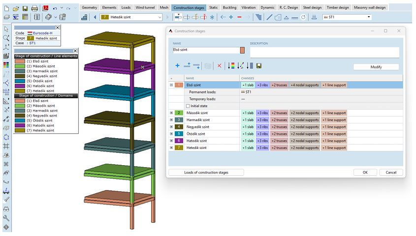
New Module - STG module
Considering construction phases is especially important during the design process when the structural framework differs from the final state or structural elements are subjected to significantly different loading conditions during construction (e.g., material storage, cranes, temporary supports, lifting, etc.). Neglecting these effects and conditions can lead to significant errors and incorrect evaluation of structural compliance. Traditionally, a structural model is often created that includes all structural elements. During finite element analysis, all loads are applied to this model, which may result in unrealistic internal forces compared to reality. Modeling construction processes can help address such issues. In this approach, separate sub-models corresponding to individual construction phases are analyzed separately, and the results are then combined. This allows phase-by-phase consideration of elements being constructed, demolished, or strenghtened. Additionally, the effects of construction loads and changes in the structural framework can be accurately assessed.
Beyond modeling construction processes, the module also enables:
- Modeling demolition processes
- Analyzing partially demolished and reinforced structures
- Examining structural strenghtenings or replacements, and verifying the strenghtened structure Assessing structural damage (e.g., checking corroded steel structures)
- Evaluating progressive collapse
- Analyzing bridge launching
New Features in Existing Modules
SOIL module
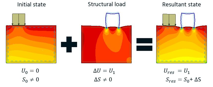
Modeling of initial state AXISVM X8 provides the capability to consider the initial state of the soil (accounting for its self-weight and any previous loads, meaning it is already under stress, but the deformation is assumed to have already occurred and is considered zero). If construction phases are defined in the model (requiring the STG module), a separate construction state must be created to calculate the initial soil condition, where the initial state consideration can be enabled. If the model does not include construction phases but does contain a soil modeling domain, a dialog box must be used before analysis to define which load case includes the soil’s self-weight and any previous loads that result in the initial state.
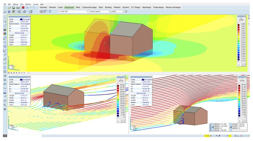
WIND module
- Separate time tracking for each WIND load case, displaying the time spent in sub-processes after the calculation
- Real-time progress indication in the taskbar during analysis, similar to structural analysis calculations.
- Streamline settings adjustable per load case and per analysis
- Improved mesh quality control and automatic settings for better convergence. Poor-quality meshes can result in many non-orthogonal cell connections. Once meshing is complete, the program examines the number of such cells, and if it exceeds a certain threshold, additional internal iterations are performed on the pressure equations to ensure convergence.
- New reliability test for more accurate and clearer results In many cases, results may appear correct but are actually inaccurate. Conversely, residuals may not reach the target value, yet the pressure field converges. To help users avoid uncertainty, AXISVM X8 includes a built-in verification check that provides feedback on the reliability and accuracy of the results.
- New terrain categories for German standard
SD1 module
- Automatic estimation of buckling length from the selected buckling shape Based on the results of the buckling analysis, both the buckling length factor and the buckling length can be specified. The Sdir (directional sensitivity), Sstruct (structural sensitivity), and Smode (buckling sensitivity) factors help in selecting the most relevant case.

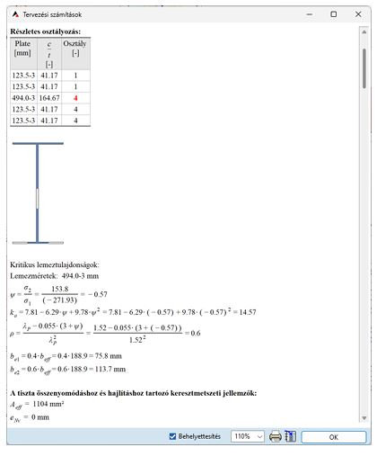
- New general section classifier algorithm
- Calculation of Von Mises stresses for class 4 cross-sections
- Details of cross section classification in the design calculation
- N, M, N+M classification switch in the steel design parameters form, to consider during the classification process
- Buckling length option
- Automatic estimation of buckling length from the selected buckling shape Based on the results of the buckling analysis, both the buckling length factor and the buckling length can be specified. The Sdir (directional sensitivity), Sstruct (structural sensitivity), and Smode (buckling sensitivity) factors help in selecting the most relevant

RC3 module
- Optional integration of punching force moving away from the support, column, wall, etc.

- New design code parameter related to the calculation of maximum punching shear resistance
RC2 module
- Reinforcement scheme wizard for reinforced concrete columns The reinforcement scheme wizard function allows the user to assign simple rebar arrangements to rectangular and circular cross-sections.

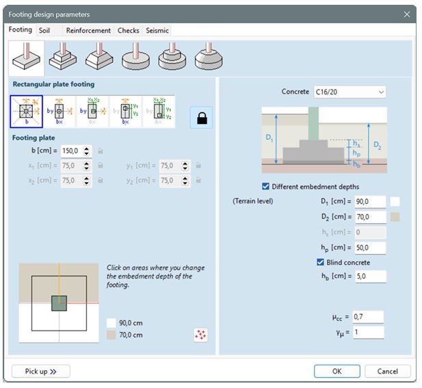
RC4 module
- Different cover depth for strip and pad footings
SWG module
- Updates for Austrian snow loads
- Terrain roughness calculation options for Polish standard
SC1 module
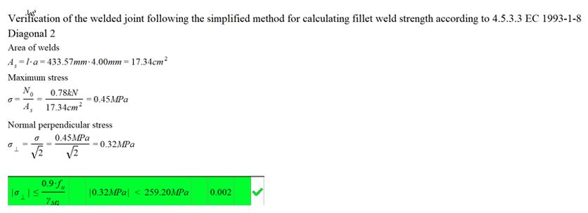
- New verification for the welds of truss connections
- Optional use of connection stiffnesses calculated in the SC1 connection design module to update the end release conditions of line elements in the structural model of the global model space
- Verification of connections for final stage (STG module) (April 2025)
New feature package to enhance user experience:
- Rhino preview for AXISVM components
- User defined model parts and folders
- Easier identification of parametric elements in AXISVM (select/deselect items)
- Access to the content of a saved axs file (import and use items, define loads)
New feature package to expand loads related components
- Moving loads
- Nodal mass o Fault in length
- Line tension/compression o Influence line load
- Concentrated load on surface elements
- Domain or load panel polyline loads may be associated to structural members
New feature package to improve general experience
- Selected material, cross section and CLT panel name is displayed on the component
- Warping characteristics
- Updates related to result import from AXISVM
Clipping regions With clipping regions, a slice of the model enclosed by one, two, or three interactively adjustable cutting plane pairs can be displayed. Clipping regions allow for a quick exploration of the internal parts of the structure, including their results if needed.


Drone mode
The drone helps to check the structural model, and in particular the inside of the structure, and is also a good tool the demonstrate the structure
Video: https://www.youtube.com/watch?v=w-HLK3DpxXs
Further developments
- Contact elements and rigid bodies also have geometric stiffness
- Winkler (Steinbrenner)
- Additional colors for graphic symbols
- The color of selected elements can be set by the user
- The name of the applied design codes are now listed among the design code parameters Convert selected arcs to straight lines
- Animation export as APNG
- Log of error and warning messages
- Consideration of consequence class in critical combinations with KFI factor
- Option to display the internal unique identifier instead of the continuous numbering when renaming/labeling elements. This identifier remains unchanged throughout the models lifecycle
- User-defined column width is now retained in tables. In the documentation, columns will continue to be automatically sized
- Transparent section option
Howdy, Stranger!
- General
- VariCAD
- 4M
- CAM
- AxisVM
- KeyCreator
- FreeLap
- 214 All Categories