Smart MEP Design for a Large-scale Residential Project using FineMEP - Part 1

Using a large-scale multistorey residential project as reference, this article highlights the practical benefits of using BIM software for MEP design for achieving a high-quality result in the shortest possible time. The software that was deployed was the FineMEP Suite comprising FineHVAC, FineSANI and FineGAS, and it was used for the piping and dimensioning of the HVAC, sanitary and gas networks, as well as for the detailed specifications of the related HVAC and plumbing equipment. Because of the combined use and critical synergies of the three applications, the design time was also significantly reduced.
The Project
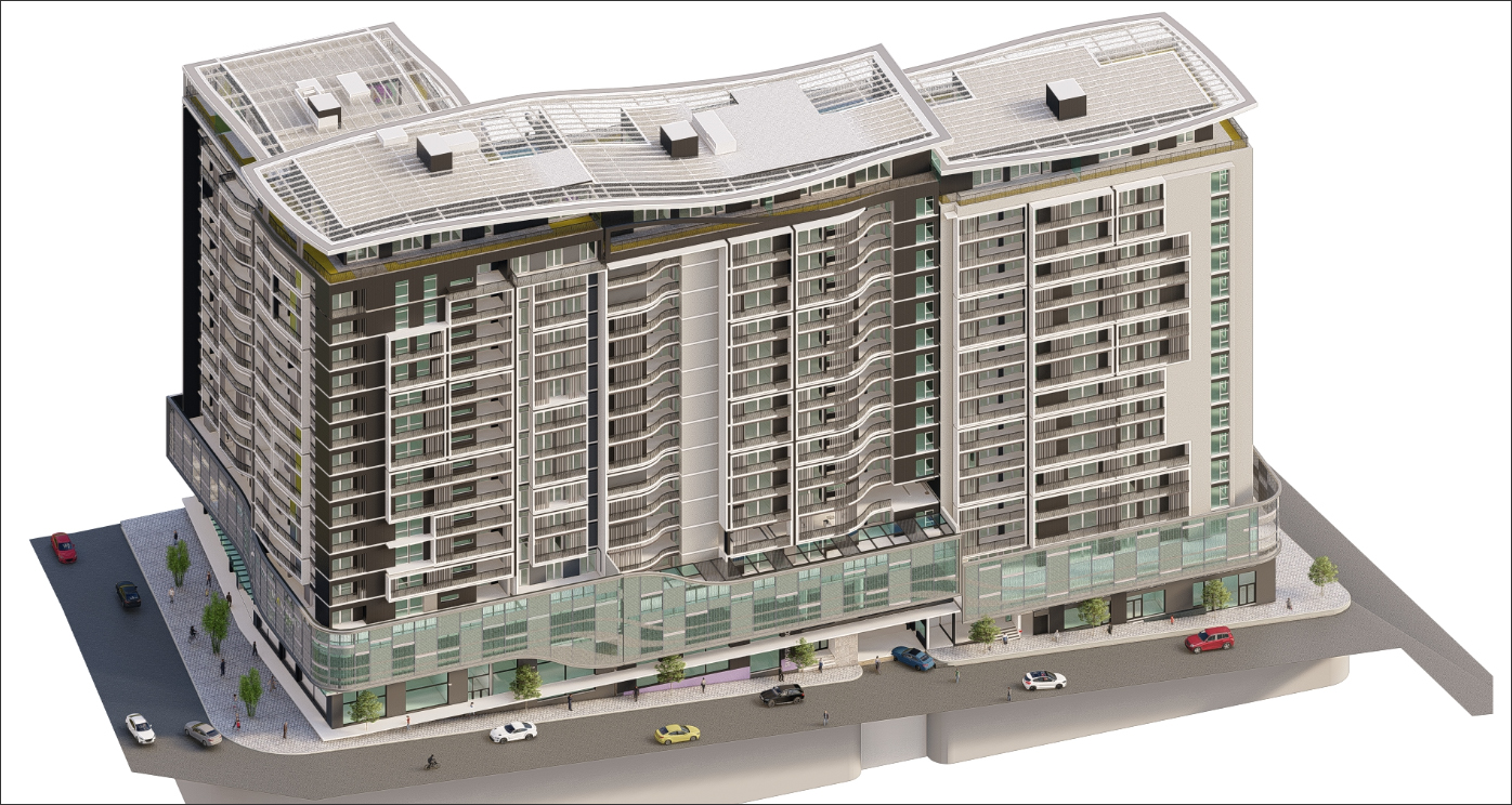
The project referenced in this article is “Mawteny Residence,” a multistorey building situated in Oran, Algeria, with over 200 apartments (Figure 1), which is currently under construction.

The project details are as follows:
- Developer: Chiali Immobilier, subsidiary of the Chiali Group
- Architecture: Sofiane Bouterfes, architect at “Le Porte à Faux”
- MEP Design: Abdelwahab Krim, engineer at “Riego Maghreb” office
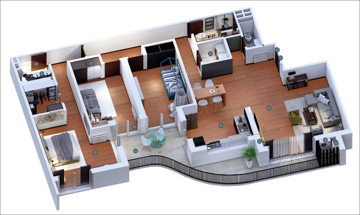
The project comprises a 17-storey residential building with 5 basement levels (23 levels in total) and 225 apartments, of which 6 are penthouses with individual pools (Figure 2). Its total volume is 93.031 m3. In addition to the apartments, the project also includes 305 parking spaces, two sports halls, a community space, a restaurant, a supermarket, and an administrative space for the residence.
Use of FineMEP
The FineMEP Suite, comprising FineHVAC, FineSANI and FineGAS, was chosen not only for its many benefits that are described in this section, but also because, first and foremost, it combines an AutoCAD-like feel and functionality with a BIM-friendly approach. While the architectural BIM model was not able to be imported, the special tools provided by FineMEP (AutoBLD group of commands) allowed the MEP BIM model to be easily created. FineMEP integrates the MEP drawing objects with their physical properties, along with their logical role in the building model, and transfers all of this intelligent data into a workable calculation component, which supports the user to figure out the best alternatives for the design.
The most important features that help to speed up the MEP design process are outlined below. These are true for all the three verticals — FineHVAC, FineSANI and FineGAS — due to their similar interface and common functionality:
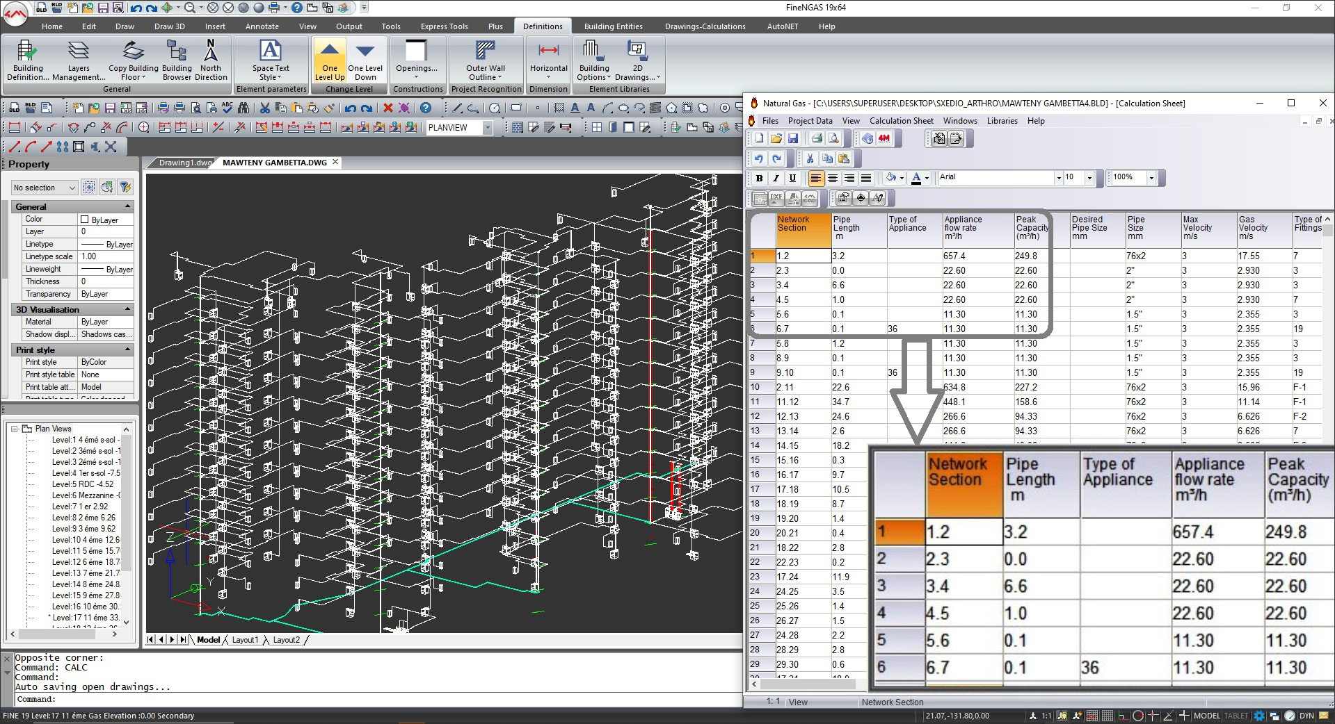
- “Recognize” the network model (segments/ nodes/ receptors) and show the numerical values of the network design parameters on the calculation sheet, which is automatically updated when any modification is made by the designer (Figure 3). Through this smart network modeling, and because of the easy supervision of every pipe segment and/or the entire network, the designer can intervene and interact without limits to see the results of different scenarios/alternatives and single out the best ones.
- Include a series of rich libraries of pipes, fittings, HVAC units, plumbing fixtures and other equipment, properly updated with a wide range of items. What is also important is that all the libraries are fully open and easily customizable by the user.
- Ensure reliable and fully documented calculations in compliance with the existing international and national standards (ASHRAE, EN, BS, DIN, etc.). In addition, the user can also compare results between the different standards.
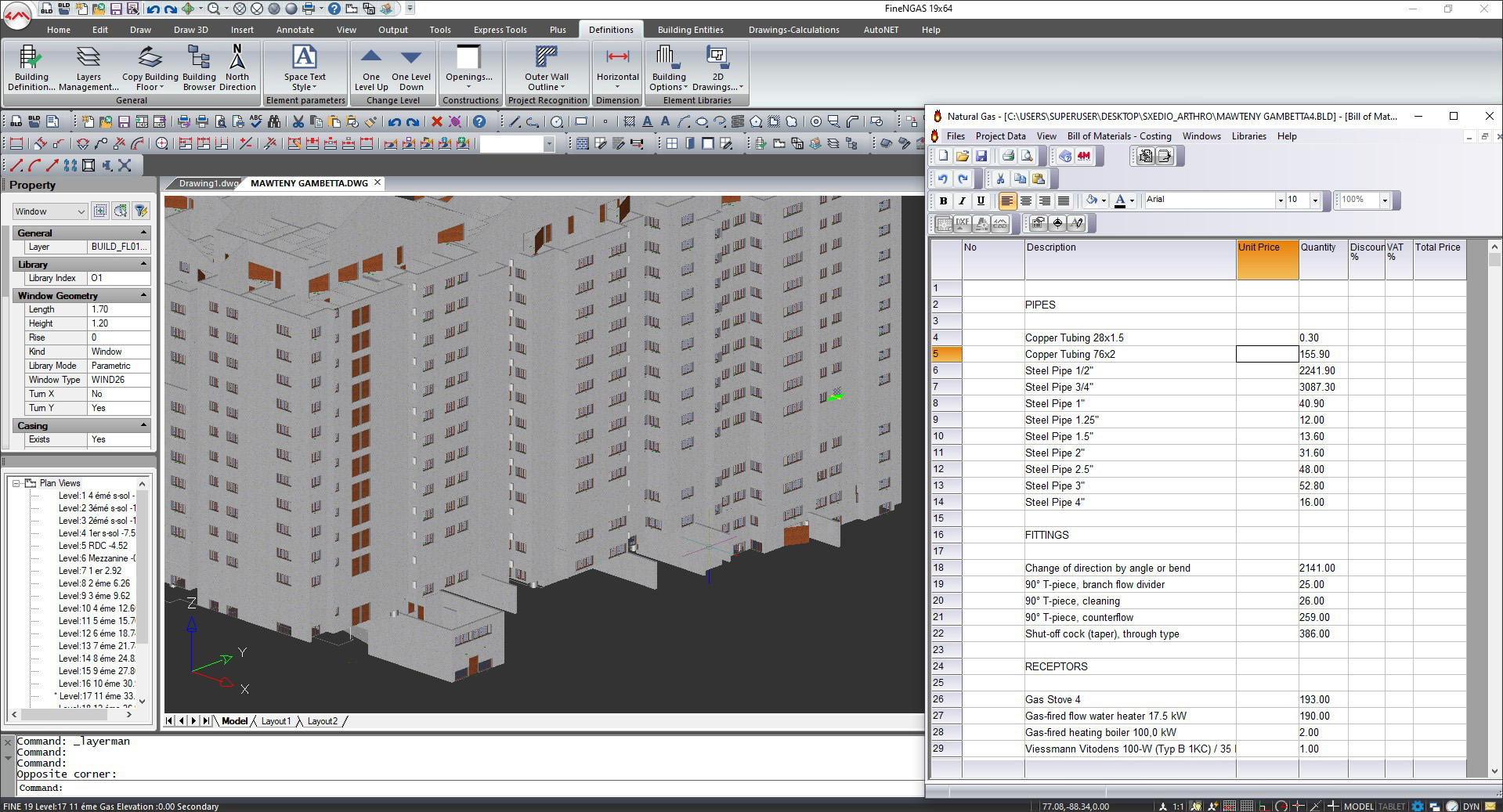
- Generate the exact quantity of the materials that need to be used in the project, such as pipes per type and size, fittings per size, number of HVAC units per type, plumbing fixtures, etc. (Figure 4).
- Provide a fully documented final printout consisting of the detailed calculation report and the full set of the case study drawings (view plans, vertical charts, isometrics etc) ready to be submitted.
- Especially in the case of the heating/cooling loads, they are also calculated automatically due to the 3D BIM building structure and the fact that the data related to the building elements (constituting spaces/apartments/levels) is transferred and calculated into the calculation sheets (figure 5).

Howdy, Stranger!
- General
- VariCAD
- 4M
- CAM
- AxisVM
- KeyCreator
- FreeLap
- 214 All Categories