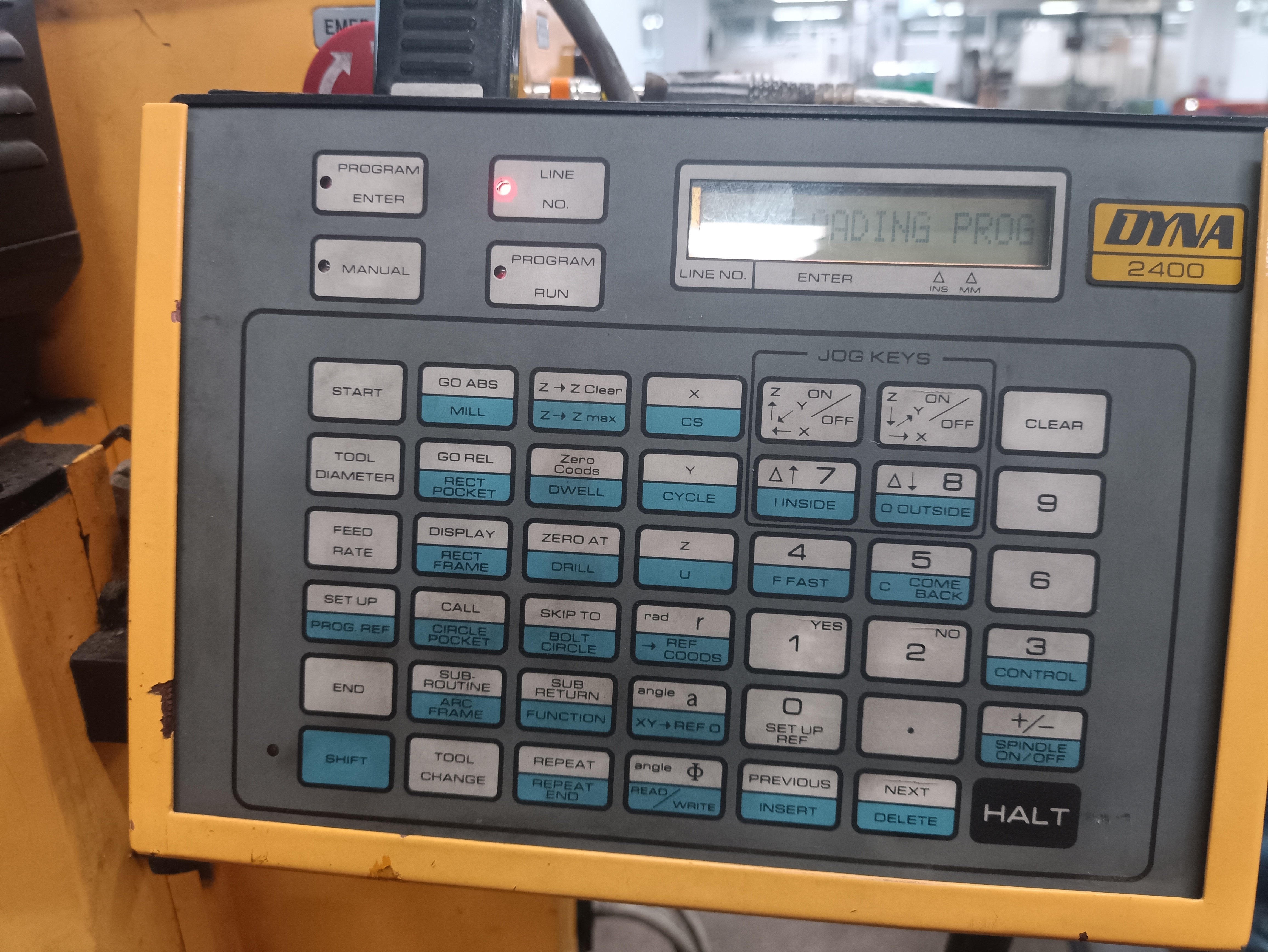
Dyna 2400 PC configuration.
I´m doing proofs with the software. It seems good but I have problems to communicate the PC with the CNC machine Dyna 2400.
It detected the port,
but it couldn't send the program. The send and receive icons are
in a grey color and can´t be pressed.
Can you help me?,
thanks in advance.
Comments
-
Jqueipo1982, This is caused due the fact that a configuration file is not loaded, you can check this – in the bottom right hand corner you see the COM port and Baud rate, what you should also see is the name of the configuration file being used. Like this

this is for a Prototrak controller but this is just an example.
You will need to create a config file that matches the parameters set in the machine tool. This is for the Baud rate (speed of transmission), number of data bit and stop bits and parity etc.
The best way is to find out what the machine is set to and then create your own, new config file. You can use one of the existing config files (I would suggest Fanuc) which is supplied as part of the standard installation.
Find out the settings on the machine tool
- Run PartMaster DNC Comms (Dcomms)
- Open existing configuration file – Fanuc
- Use the Port Setup > Port configuration – as shown here …..

- Change the settings to match your machine tool, leave the Handshake and Hardware setup as it is
- Save the new config file under a new name
Things you will to check.
I assume you are using a USB to serial converter ? Ensure that there are drivers loaded for this device and that in the Port setup, the COM port matches that found in Device Manager.
-
Jqueipo1982, check these 2 links below, with some additional information for PartMaster RS232 Configuration and Training.
https://drive.google.com/file/d/1cgCn6CWTwTwzcvhRkY5Ip_WbZp4bzASs/view?usp=sharing
https://drive.google.com/file/d/1f90ynZhiszoJCIqr_hhthnxjHiihTOxS/view?usp=sharing
-
Hello, I have tried the configuration you told me, but it's not working correctly.
The "send program" option appears, but it doesn't reach the machine. I have tried disconnecting the cable, and it says it sends and also confirms that the file has been sent.
I have attached some pictures of the process.
Do you have any further steps or suggestions?


-
Jqueipo1982, we need to know the configuration of the cable you are using.
Please confirm this,
Are you using a USB to serial converter cable from the PC ?
Are you using another cable that is plugged into the end of the USB to serial converter and then connected to the machine ?
Do you know the pinouts of this second cable ?
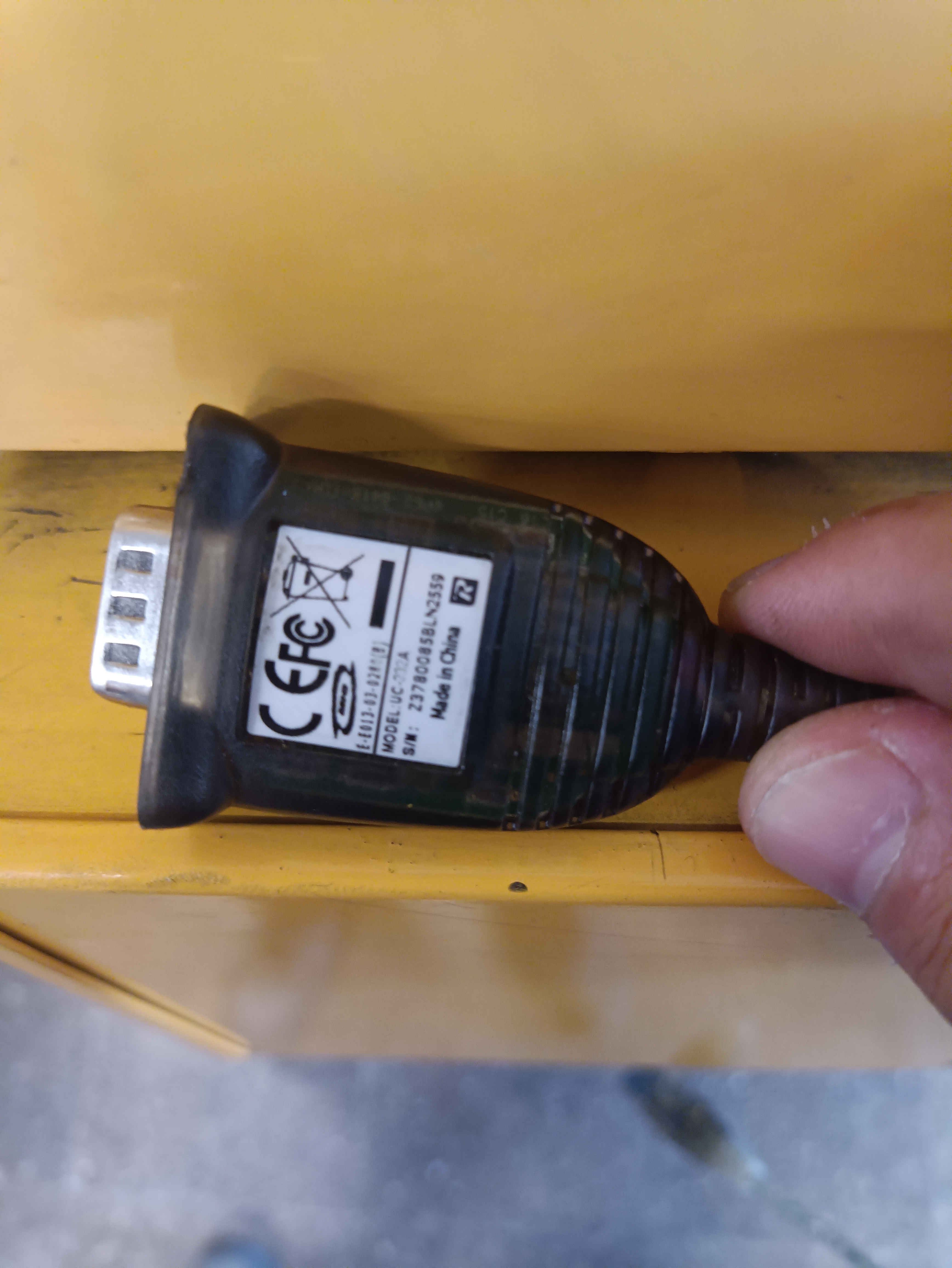
You can’t connect a USB to serial converter directly into the machine tool.
-
Hi,
Answering your first question, we are using a serial converter cable from the PC.
We are using a plug converter connected to the plugged end of if the serial usb converter.
I don´t know the pinouts.
Thanks -
Jqueipo1982,
OK, I see the problem now.
The setup you are using will not work. The USB to serial converter only provides a connection so that a 9 pin data cable can be connected between the PC and machine tool.
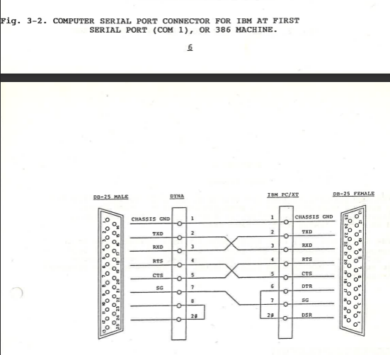
The data cable will provide the correct data signals for the 2 devices to transfer data. If you look at the diagram below you will see that the data cable will swap signals using pins 2 & 3, so that data sent from the PC using the Transmit pin – TXD 2 will be swapped with the Receive pin – RXD 3 on the machine tool. And the opposite way round when sending data from the machine tool to the PC.
Just a note – on a 25 way connector PIN2 is transmit and PIN3 is receive – on a 9 pin connector PIN2 is receive and PIN3 is transmit, so it looks like they are not being swapped over, but they are.

NOTES on Cables
The correct data cable is very important to get the comms working, a single pin can make all the difference
Here is the data cable I would use, I would assume there is an electrical department in the university that can make this for you.
You need to do this.
- Keep the USB to serial converter attached to the PC
- Ensure that the drivers for the USB cable have been loaded
- Check this by using Control Panel > Device Manager and look for the USB to serial converter entry
- Attach a data cable cable between the USB to serial converter and the machine tool
- Set the machine tool controller ready to receive data
- Run Dcomms and ensure that the Port Configuration file is loaded that matches the settings on the controller
- On the PC use Dcomms to send the G code file to the machine tool controller.
Hope this helps.
It sounds a bit complicated but once it is setup and working it will continue to work.
Howdy, Stranger!
- General
- VariCAD
- 4M
- CAM
- AxisVM
- KeyCreator
- FreeLap
- 214 All Categories
